
Technical FAQ
Is it permitted to bury MICC Cables directly into concrete or plaster?
Firstly, when cables are buried in concrete we would recommend the use of served cables as the concrete mix may be corrosive to copper. If the cables are to be buried in plaster we would have no reservations about using bare copper cables as normal wall plasters are not corrosive to copper. The cables would not normally require any further mechanical protection when buried in plaster or concrete.
Can I use bare copper MICC Cable on a galvanized cable tray?
Electrolytic action may take place when the copper sheath is in contact with the galvanized (zinc) plating of the cable tray. The reason for this is that the electropotential series indicates that zinc is anodic to copper and therefore preferential corrosion of the zinc plating may occur. This action will not affect the MICC Cable sheath but may cause superficial corrosion of the cable tray.
The presence of moisture is essential to produce electrolytic action, therefore, in dry conditions, this action will not occur. If moisture is present, then electrolytic action will take place, but the extent of any corrosion is dependent upon the relative areas of the two metals and the conductivity of the electrolyte (moisture in this instance). In the case of MICC Cable on a cable tray, the area of the cable sheath is small compared with the area of the tray, therefore the degree of corrosion will be low.
In conclusion, electrolytic action will not occur in dry conditions, but damp conditions may result in the tray deteriorating more rapidly than expected. The use of bare copper sheathed MICC Cable on a galvanized tray is therefore not normally a problem.
How do MICC Cables react if they are subjected to radiation?
The cable is manufactured from inorganic materials (copper and magnesium oxide) which make the cable highly resistant to radiation. The seals on the end do have organic compounds but we have successfully tested seals to a radiation dose of 950
megarads without losing their sealing properties. Such a seal consists of a standard seal with the standard PVC sleeving being replaced by silicone elastomer glass braided sleeving.
On some MICC Cables that I have installed, the sheath of the cable seems to run quite warm. At what temperature does MICC normally operate?
The exposed to touch current ratings of MICC Cables are based on the sheath temperature of the cable rising by 50°C. The ambient temperature is assumed to be 40°C therefore the sheath can attain 90°C (see section 310.15 tables 310.16, 310.17, and 310.20 of the NEC) when fully loaded. 90°C is hot to the touch but considered normal and acceptable for connected equipment. If required an estimation of the expected sheath temperature at any level of loading can be calculated using the following formulae,
(Ib2/Iz2) x 50°C + ambient temperature (°C)
where
Ib = Load to be carried (amps)
Iz = Effective rating of cable (amps)
What value of IR should I expect on a MICC Cable after installation?
Firstly, the cable should not be tested until permanent seals have been fitted to both ends of the cable. An insulation test carried out 24 hours after the cable has been terminated, should achieve a value above 100 MΩ @500VDC.
What considerations do I need to make for single-core cables carrying large currents (>200A)?
When a ferromagnetic material such as a termination plate in a steel or stainless enclosure is subject to an alternating magnetic field from the current in the cable terminating into the enclosure there are two potential sources of loss
- hysteresis requires energy to overcome magnetic pole rotation and this ultimately appears as heat and
- eddy current losses where the rotating magnetic flux causes induced eddy currents which cause energy loss and also appear as heat.
These heating losses are only significant in cables carrying over 200A so these considerations typically apply to single-core cables of size 1AWG and above.
When cables are required to pass through termination plates in enclosures or mounting plates for locating, for example, cable glands, several techniques can be used to minimize these losses.
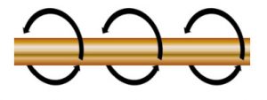
With ferromagnetic termination plates, one way to significantly reduce these losses is to cut slots between adjacent holes in this manner:-

Another way is to avoid the use of ferromagnetic material as the termination plate and in this case, we would recommend brass or aluminum provided it can adequately support the weight and forces involved in terminating the cables into such a plate. In damp or saline conditions care should be taken to avoid any galvanic action between such plates and the steel enclosure. This can be achieved with some corrosion protection coatings – pay attention to the continuance of the earthing of the plate to the enclosure. Plastic (HDPE or ABS) enclosures may be used but again must be mechanically robust enough to support such large cables.
How long will MICC Cable last in service?
As previously stated, the cables are made from inorganic materials and therefore do not deteriorate with age. There are many installations throughout the world that are over 50 years old and the cable is in perfect condition. In some cases, on very old installations the original neoprene conductor insulating sleeves may have deteriorated but it is a comparatively simple matter to renew these with the present-day standard sleeving.
Are MICC Cables fireproof?
MICC Cables will continue to operate in a fire at temperatures approaching the melting point of copper (1083°C). While certain organic insulated cables claim to be ‘fire resistant’ or ‘high temperature’, MICC Cable is truly a fire survival cable.
Can MICC Cable be buried directly in the ground?
MICC Cables are suitable for burying in the ground and are subject to the same procedures as other cables regarding the depth of the trench, mechanical protection, and identification of routes. We would always recommend served cable as some soils can contain elements corrosive to copper.
What is the minimum bending radius for MICC Cables?
The usual minimum bending radius specified is typically equal to six times the diameter of the cable sheath. This will allow the cable to be re-bent if necessary.
What are the effects of transient overvoltage surges on MI cables, typically found in generation and control?
It is common knowledge that inductive circuits produce transient voltages when the current flowing in them is suddenly interrupted and that under adverse conditions these voltage surges can cause a breakdown in various circuit components. This phenomenon is recognized in the various regulations and it is the designers/installers’ responsibility to ensure compatibility between circuit components. When such circuits are wired with, say new PVC cable, the cable has normally sufficient reserve of voltage withstand to ensure that damage falls elsewhere in the system. Thus, unexplained breakdowns in such components as electric motors, chokes, resistors, transformers, switches, and contactors are by no means unknown, although it is common to attribute them vaguely to overloading or to accept them without explanation.
The factors influencing the generation of surges are many and complex; the point in the current cycle at which switching occurs, the exact moment of separation of the contact points, and the presence of stray damping and other losses in the circuit are but a few of the contributory factors. Thus, many pieces of equipment that are theoretically capable of producing troublesome surges, only occasionally do so in practice. Many pieces of equipment that are capable of causing trouble will run for many years, without encountering the conditions which could cause failure.
The installations most likely to give trouble are those which are most frequently switched. Examples are air conditioning installations, refrigeration systems, and others where equipment is cycled every few minutes. When MI cable is used it may sometimes happen, although this is not necessarily always the case, that the cable itself is the circuit component with the lowest surge voltage withstand. In such cases, a cable failure may result.
Such failures are rare, however, each incident causes annoyance and inconvenience to the user. The best cure is to suppress voltage surges at the source and it seems likely that public influence and regulations will move progressively in this direction.
Some manufacturers of equipment are reluctant to incur the very small additional cost in time and money of including the necessary suppressors in their equipment and prefer to take no action in this matter, leaving all other circuit components to take their chance with surges which may amount to many kilovolts. To use high voltage cable in every meter of wiring and to build into all other components adequate insulation against such excess voltages would be an impractical and unrealistic way out of the problem. Hence in the present state of affairs, it is
left to the user, often without proper guidance, to take the appropriate action.
MICC Mineral Insulated Cables offer the safest, most durable, and neatest wiring cable system yet devised and these cables, together with other more expensive circuit components, can be simply and inexpensively protected from surges by the use of standard surge voltage suppressors.
Long experience has shown that trouble arises primarily from certain well-defined types of equipment.
There are:
Fractional Horse Power Star Connected Three Phase Motors
Experience indicates that star-connected motors above 3hp rating, all delta connected and single-phase motors do not need suppression. However, star-connected motors of smaller sizes (particularly in the fractional horsepower range) may easily give rise to switching surges of dangerous magnitude.
Surge suppressors are a reliable way of overcoming the problem.
Contactors
Contactor coils are a likely source of voltage surges.
Lighting
The choke can produce high voltage surges. In many fittings, these are absorbed by the parallel-connected power factor correction capacitor and no surge suppressors are required. However, certain types do not incorporate a power factor correction capacitor and the voltage surges generated within the striking circuits are not necessarily confined to the fittings. On the type of installation in which the control gear is situated remote from the associated discharge lamp, it is not possible to give protection to the connecting cable. It is therefore essential that a suitable High Voltage cable is used.
Dual Speed Fan Motors
Experience shows that dual-speed fan motors may produce significant transients. It is recommended that surge suppressors are fitted to both sets of windings.
Initial Installation
Perhaps the most widespread misconception regarding surge suppression is that it is an expensive additional operation. On the contrary, a small outlay in time and material is sufficient to give an essential safety factor to the electrical installation as a whole. Suppressors are recommended for small three-phase star-connected motors and contactor coils.
Existing Installation
MI Cable has the unique ability to recover from a flashover. Some rare cases have occurred when numerous surge strikes on the same cable have reduced the insulation’s withstand against overvoltage, and resulted in fuse failure. Under normal operating conditions the cable continues to work satisfactorily, but it may be desirable to fit one of the above suppressors to protect the cable against further surge voltages. Before fitting the suppressor, the condition of the cable should be ascertained by testing the IR at 500 volts and 1000 volts and comparing the two readings. A much lower reading at 1000 volts will indicate that the voltage withstands of the cable have been permanently reduced and that it cannot be protected from further voltage surges by one of the above suppressors.
Office Address
26695 Eckel Road, Suite B, Perrysburg,
Ohio 43551
USA
[email protected]
Phone: 567-331-0101
Cell: (419) 575-7220